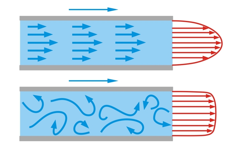
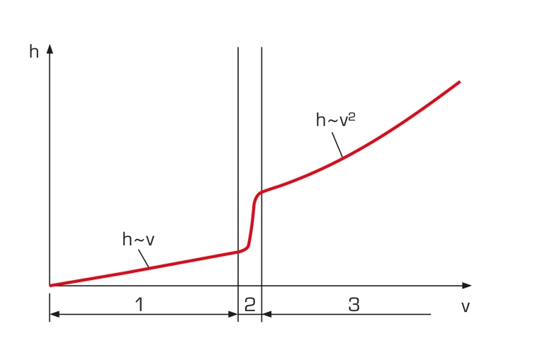
During flow through pipes, pressure losses occur due to internal friction and friction between the fluid and the wall. When calculating pressure losses, we need to know the friction coefficient, a dimensionless number. The friction coefficient is determined with the aid of the Reynolds number, which describes the ratio of inertia forces to friction forces.
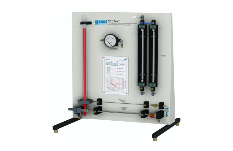
HM 150.01 enables the study of the relationship between pressure loss due to fluid friction and velocity in the pipe flow. Additionally, the pipe friction coefficient is determined.
The experimental unit includes two pipe sections with different diameters. The large diameter pipe section is used to analyse turbulent flows and is supplied directly from the water supply. The pipe section for laminar flow is supplied via a tank with overflow. This ensures the constant inlet pressure required for laminar flow. A gate valve or flow control valve can be used to adjust the flow rate. The Reynolds number and the pipe friction coefficient are determined from the flow rate and pressure loss.
The pressures in laminar flow are measured with twin tube manometers. In turbulent flow, the pressure is read on a dial-gauge manometer.
The experimental unit is positioned easily and securely on the work surface of the HM 150 base module. The water is supplied and the flow rate measured by HM 150. Alternatively, the experimental unit can be operated by the laboratory supply.


