


In rotating machines such as turbines or pumps, vibrations due to imbalance lead to comfort problems or even damage related to overloading. The imbalance of a rotating machine part may cause harmful vibrations in the entire machine. A familiar example is unbalanced tyres on a car. These cause annoying and unpleasant vibrations in the steering. This is why almost all rotating parts are balanced. If this balancing is done not on a particular machine but directly on the machine in operation located on-site, it is known as field balancing. Field balancing is done in four steps. In the first step, the vibrations are used to measure the initial imbalance. In the second step, additional known test imbalances are applied and the system is measured again. In the third step, the balancing is calculated from these two measurements and is applied. The fourth step is a control run to check whether the balancing has been successful.
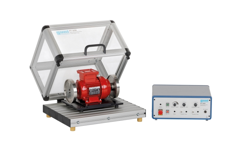
The core of the PT 502 unit comprises two flywheels that are driven by an electric motor. Defined imbalances can be attached to the flywheels. At the foot of the motor are two acceleration sensors that measure the imbalance vibrations. The speed is measured by an optical sensor. The motor is mounted on the base plate with vibration-damping rubber elements. The unit is driven at variable speed by a frequency converter.
The measured values are transmitted directly to a PC via USB, where they can be analysed using the vibration analysis software that comes included. This analysis software has the following features: dual-channel oscilloscope for investigations in the time range, dual-channel spectrum analyser for investigations in the frequency range, vibration amplifier and balancing module for single and two-plane balancing.