


Para poder identificar fallos eléctricos en instalaciones frigoríficas se requieren amplios conocimientos. Aparte del montaje y el funcionamiento de los componentes eléctricos individuales, estos conocimientos también abarcan la lectura de esquemas de conexiones. Por medio de la instalación ET 174 se pueden adquirir estos conocimientos.
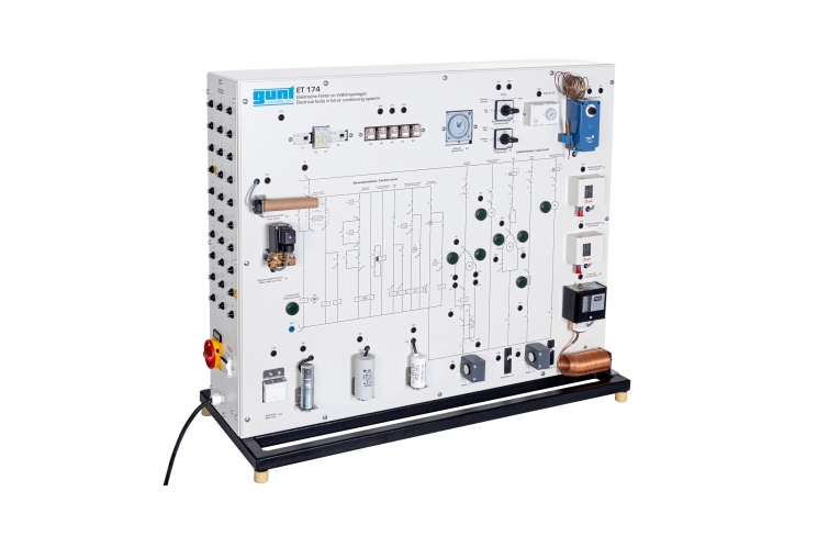
ET 174 muestra el circuito eléctrico de una instalación de aire acondi-cionado completa con función de bomba de calor. Los circuitos de man-do existen realmente. Los componentes en los circuitos de carga son simulados (p.ej. compresor, calentador, válvula reversible de 4 vías).
La instalación de aire acondicionado con función de bomba de calor re-frigera en el verano y calienta en el invierno. En el modo de calefacción, el temporizador de descongelación inicia la descongelación por gas caliente mediante una breve conmutación de la válvula reversible de 4 vías. En caso de temperaturas exteriores muy bajas, una calefacción eléctrica adicional se activa en el modo de calefacción. En caso de una humedad del aire baja, el higrostato activa la función de humectación.
Unos dispositivos de protección típicos, tales como interruptores pro-tectores y detectores de hielo, completan el circuito eléctrico. El estado de servicio de los componentes simulados es indicado por lámparas en el esquema de conexiones que se encuentra en la placa frontal.
La simulación de 30 diferentes fallos, como p. ej. la rotura de bobina del motor o un relé defectuoso, es posible. Para la identificación de fallos se comprueban las tensiones o resistencias en los conectores de laboratorio con ayuda de un multímetro. La ilustración del esquema de conexiones en la placa frontal facilita la asignación de los puntos de medición.